Train of thought

Modelling foreign railways whilst a club member in the UK.

I have been a member of four different clubs in the UK over the past thirty-five years or so. During which time I have mainly modelled in H0 scale and have been called for it!! Comments like “watch out for Stuka’s” when running late seventies/early eighties East German steam, yes – really!
“Here we go again” was another one – why? Do folk really not like to see models of trains unless it’s the typical, ordinary, everyday models they already know very well? Don’t they want to learn about anything new or different?
Of course, the worse ones are not repeatable here but needless to say were particularly rude.
I guess that after a while, one develops a fairly thick skin but it is still necessary to retaliate in some small way or another. So, standard replies used to vary from “at least my stuff works”, “my stuff has the correct scale/gauge ratio” to “I’d rather have one of mine than twenty of yours” and “at least mine isn’t narrow gauge”. However, I’d rather not have to fight back – really, I wouldn’t.
I found the attitude varied from club to club, larger, better developed clubs could be expected to have at least some other members who were aware of railways beyond the shores of the UK but smaller clubs that I have been part of, seemed totally unaware.

Is it my fault?
I’m not shy of showing the capabilities of some of my H0 scale models off (should I be?) and have been proud to demonstrate both the prowess and the slow running qualities of certain models. At an old club near Derby, I did successfully run a 100 wagon US freight on the main 00 gauge layout but does that kind of thing impress certain people? No.
I’ve told people about my Gutzold BR58.30 taking some five minutes to traverse one inch, again to blank faces.

Perhaps it jealousy?
Certainly, some of my ‘Continental’ models have cost me a lot of money however, I don’t splash the cash on fancy new cars, new gadgets or season tickets to sporting events. How I choose to spend my money is my business, thank you and one of my European locos will last a heck of a lot longer than the latest Hornby train set!
I inherited one lone Fleischmann pacific from a very dear friend, several years ago now. I am saving it until it’s either 25th or 30th anniversary when I shall put it on the track and see how it performs after such a long time in storage.

I think the real problem is simply ignorance!
I must point out here, that I am not exactly “educated” myself – I left school at 14 with no qualifications whatsoever but later, when I returned to the UK, I got some GCSEs and eventually, yes – I went to university but I had to fight for that, it wasn’t given to me by any means.
If you travel across Europe, you will meet many people, a lot of whom will speak at least some English and quite likely, other languages too. European people are much more open minded about such things, aware of other places and accepting of them.
Whereas, when you travel across the UK or even, the USA – you will only meet people who can speak English. Okay, in the southern USA, you can meet some folk who will also speak Spanish! Canada, I have no experience of bar some cousins but I gather that most folk speak English OR French, rarely both?
So! Because the “English*” can’t or won’t speak another language, they choose to ignore countries and railway systems thereof, they cannot understand.
But why not try?

When I was at school, IIRC, I had the choice of “French” or “German” classes and I chose “French” as I had some experience, having lived there!
I did find though that my school “French” was rather different from my experience of the real thing, perhaps the curriculum didn’t need you to be capable of living there?
I also recall during some general lessons at a previous school, being told off for correcting the teachers’ incorrect pronunciation of a “J”!!!
I only mention this to demonstrate that if a school teacher, teaching Spanish didn’t know how to say “J” correctly, then what hope for the rest of the population?
Further demonstrating the small-mindedness of this little island, was the experience I had fairly recently of helping to exhibit a good quality French layout (of a French prototype!) at the large Warley show. This actually did get a decent reception but adjacent to us was a “model” based upon a Dutch masters painting, which has to be regarded as one of the finest model railways anywhere, ever.
Whilst most of the rest of us spent some time, gazing at this masterpiece, one of our helpers, from one of these “small clubs” previously mentioned, preferred to spend his free time buying 00 scale blue diesels! “Oh, that” he said when queried later, “yeah – I wasn’t interested”!!!

There’s an old saying – you can take a horse to water but you sure can’t make it drink!

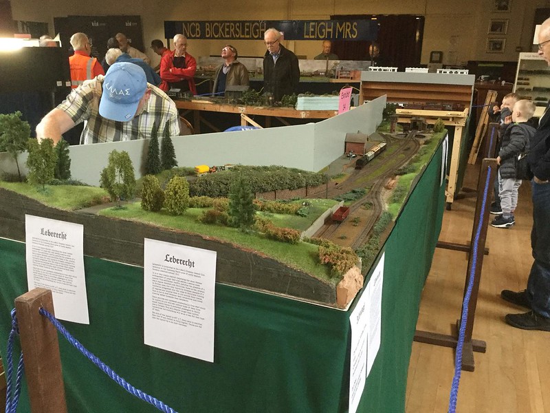
Well, that’s my take on modelling “foreign” as a club member. Now, exhibiting a “foreign” layout, that’s another story!

*Lumped in with the “English” (speakers), are the Scots, Welsh, Irish, Kiwis, Aussies, Yanks and so forth, sorry!

Stress!

Now to try and describe the stress that I went through upon my return from holiday!
Despite having had a wonderful break away from everything, when my wife and I returned to the UK, my feelings of anxiety returned with a vengeance as there was so much still to do. We also had some rather rainy weather to contend with too that caused a delay in collecting the layout but I busied myself clearing the kitchen as my lovely wife Bev, had allowed me to assemble the layout here rather than down in the big shed. It meant that work could be carried out in comfort.
When I did get over to Doug’s and laid eyes on the layout, I was stunned! He really had done an excellent job, I must say.
After some discussion, we added some further vegetation to certain parts of the scenery and changed some grass colours to darker shades, other than that, I was very satisfied with how the scenery looked.
We then transferred the layout over to my kitchen and set it all up again. This at least was good practice for the exhibition.

Leberecht

I now had to start working my way through the extensive list of jobs I had written whilst in Greece, the first job being to ensure greater reliability of the action of the points. My first thought was to superglue the actuating rod to the tie-bar. Big mistake! What had been inadequate performance previously was now rendered completely useless. Bev came to the rescue thankfully, with her suggestion for more substantial actuating rods, sourced from her jewellery making collection. A bit of filing and cutting later, the first new rod was installed and worked beautifully, thanks Bev! This was repeated for all the other points, what a relief when they all worked.
Next, I had to assemble the station building but first, I wanted to recreate mortar lines in the brickwork. Some folk use “Jif” but I had heard good reports about “Roberts Brick Mortar formula” so I gave it a go. Unfortunately, due to the pressures on my time, I left it longer than needed so it set harder than it should have been but scraping with a toothpick resolved this issue and I was quite satisfied with the results. It was then very quick and easy to assemble the flat-pack parts of the station building, I was very pleased with how it then looked. Small details still needed to be done but it was at a good state for the show, especially after I gave it a quick blast of weathering from my airbrush.

Leberecht

Leberecht

Boosted by this, I then gave the mortar treatment to the loco shed and all the components for the water tower, which I then assembled quickly but accurately – I’ve never built a building so fast! I hasten to add that I had built the loco shed previously, it was only the water tower I built in a hurry. These two were also treated to a quick airbrushing for a much improved appearance.

Leberecht at Leigh show Sept 2018

Leberecht at Leigh show Sept 2018

Whilst I was doing these jobs, I was also working on many other jobs, some of which caused a major meltdown like when I initially connected up my Roco Z21 digital controller. Previously during testing, I had always used my trusty NCE but I thought that Doug would prefer to use the Roco Multi-Maus, hence the Z21.
Unfortunately, it turned out that I had connected on of the serial leads into the wrong socket on the wireless (wi-fi) terminal so there were red lights flashing on the main black box! I thought this meant there was a major ‘short’ on the layout so panic ensued. Fortunately, Doug gave me a talk-down and, feeling calmer, I re-read the instructions, connected everything correctly and voila! We were in action and the electrics and points were now working as they should.
I also finally wired up the turntable and was very pleased when it worked perfectly, what a relief!
Having gotten so far, I really wanted to fit my Viessmann signal as I really love the action on these mechanisms but I only had a 12mm drill bit. I managed to enlarge the hole by waggling the drill bit but sadly, the signal went in at a slight angle, never mind! Unfortunately, I then discovered that the output of my Lenz accessory decoders was incorrect to drive my signal, Grr!

Leberecht

Meanwhile, Bev was busy finishing the painting of the back-scene boards and also making a front ‘skirt’ from some green cloth that I had bought for my US layout but never got around to doing ‘properly’, this entailed cutting to the correct height, stitching the edges and fitting ’Velcro’ so the skirt can be added and removed easily.

Leberecht at Leigh show Sept 2018

Also, Doug and Bev did some ’tidy up’ painting of the baseboard edges where there were still pink foam edges on display(!) along with additional ballasting right up to scenery sections, buildings and so on.
I had wanted to at least get my freight stock weathered before the show but time was running so late, I only had chance to make sure everything was fitted with Kadee couplings and the one loco I knew was iffy, got a clean of wheels and pick-ups.
By now, we had reached Friday tea time so it was time to get the layout over to the exhibition venue.
Until next time.

Applying Greenery

I cannot give a very detailed description of the next stages of the layout’s construction as that was in the capable hands of my scenery guru, Doug Coombes, I can only show some photos he sent me as updates while I was getting some relaxation in.

I do know that Doug spent some time studying and practicing the techniques of Josef Brandl and Gordon Gravett but this was long ago although I believe he gave himself a refresher course before starting work.

First, Doug painted the plaster castings.
Scenery on Leberecht

You can see how difficult it was to disguise my crude attempt at filling the gaps between the castings, sadly this caused Doug much angst and he had to paint over my filler several times, leading to a darker finish than was otherwise necessary or wanted.

Scenery on Leberecht

Scenery on Leberecht

Fortunately, I had not used any filler on the retaining walls so they came out much more satisfactorily and won’t need to be redone.

Next came the grassing with the electrostatic gun.

Greece 2018

Greece 2018

While I’m working rapidly through the photos, I must point out there was a lot of work just to get to this stage. Each static gun use only covers a relatively small area of terrain, partly because the charge fades away if working far from the earthing nail and partly because of the need to work onto wet PVA.

After grassing came the weeding, that is adding weeds, not removing them.

Greece 2018

Greece 2018

Next, trees were added and more weeds around the bases of the trees.

Greece 2018

Greece 2018

I had researched the types of tree to be found on Luneburg Heath and they included Spruce, Birch, Beech and Juniper. Most of these were available from MBR Model of Poland https://mbrmodel.eu/en/ and I was very grateful that they had them all in stock and could ship very quickly indeed, this certainly saved my bacon. It may have been ‘nice’ to build my own trees but I have neither the experience, time nor motivation to do so when such magnificent models are available for a fair price.

Probably the most important signature flora on Luneburg Heath however, is the heather which appears to grow everywhere and puts on a magnificent display, MBR do a purple shrub that looked a good match for the original.

Greece 2018

Greece 2018

Actually, I think my heather is a still little tall despite Doug cutting it down from the original but it is the best I will get until Doug or I learn how to make it ourselves so it will stay for the time being.

Finally, Doug then carefully masked off my track and added additional fixatives to secure the greenery and added further detailing such as ‘flowers’, ‘weeds’ and grass between the tracks and so forth.

Greece 2018

Scenery on Leberecht CC. Doug Coombes

While Doug was busy in the UK, I took my time in Greece to assemble in ‘flat pack’ form, my station building. Unfortunately, I didn’t take any photos, sorry. I had to build it in this way as I was so scared of it getting damaged on the flight home as it would have been too late to repair it by then.

Next, the return home with just two full days prior to the layouts first exhibition appearance. Never again will I subject myself to this level of stress.

All pictures © Doug Coombes.

Plaster Castings

Several years ago, my good friend Doug Coombes, bought lots of silicon rubber moulds from Werkstatt Spörle, a sadly now defunct company*. These moulds can be used to make the most exquisite plaster castings of all sorts of model infrastructure using fine quality casting or ‘dental’ plaster.
One of the drawbacks of doings things this way, besides the castings being quite fragile, is the finished item is a quite stark white! To try and get around this we decided to experiment with adding dry powder paint to the plaster mix.
The first batch we did was with 3 grams of paint to 100 grams of plaster but this was rather dark so we then moved on to 1 gram paint per 100 gram plaster. This was better but on reflection maybe we should have tried 1.5 gram per 100? Time was short so we pressed on with this 1% mix.

Doug provided the materials and methods, I mainly just did the donkey work as well as the quality weighing scale, casting table and other tools. My first castings were a little too thick as I was learning the techniques.
Within a few days, I had made quite a number of castings for the platforms, retaining walls, roadways and loading dock hard standing. I actually made rather more than was needed as I suspected we may have some breakages but, working carefully, I don’t recall any.

Now the hard work began!
Obviously, a plaster casting cannot bend at all and I needed to create some curved sections. So, I resolved to cut some sections into short strips, sand a fine taper onto one edge then reassemble – easier said than done. The main tools used were my fine modelling saw, fine sandpaper and a decent file. Individually, one piece of plaster only takes a couple of minutes to do but when I counted up the number of pieces used in my cutting, there were over fifty items – eek! That’s where the time goes.

I found the worst problem for me was that this plaster is so fine, the dust created gets everywhere and really sucks the moisture out of your skin, next time – I must wear rubber gloves like the medical professionals wear. Be warned, especially if you have sensitive skin or skin conditions.

After I had laid the platform and created ramps for the ends of the platform, despite my best (too rapid?) efforts, I had some unsightly gaps between the individual pieces so I went over all these gaps with my white squadron putty – which I had used previously without any problems. It’s lovely stuff for plastic modelling but not for plaster modelling!
When Doug came to paint the castings, he was cursing me left & right for doing this as his paint would not cover the putty! Oops! Any future gaps MUST be filled with very liquid plaster. Eventually, he was able to cover the differences but it needed much more paint than would have been normal and so a lot of detail was lost, sadly. For this reason, a lot of my castings will eventually have to be redone.
Anyway, my much needed holiday was rapidly approaching so the layout was transported over to Doug’s house so he could apply the greenery.
Next time,
John.

*Similar moulds can now be obtained from these sites;
https://www.modellbaushop-joachim.de/
https://langmesser-modellwelt.de/silikonformen-h0/?p=5

Groundworks

Having now finished my first show with this layout, it is now that I need to go back in time (so to speak) and show how I prepared the layout for the scenery.
First, I painted a thick layer of PVA all over the pink foam areas and coated this with strips of plaster impregnated cloth. Some I did wet but after a while, I decided it might be better to do it dry and mist a small amount of water on afterwards – this seemed more effective.
Once this was done and quite dry, I mixed up some plaster with ‘brown’ cement die and liberally painted a fairly thick coat all over.

You can also see that I have prepared where the roadways will go (the remaining pink areas). This is for plaster castings that MUST be laid onto a flat surface so any gradients or angles were carefully prepared with a surform.

You can see that I also incorporated some-cut down plaster ‘rock’ castings too.

The ‘soil’ is just that, collected from my garden, ground, sieved and baked at a low temperature for an hour or so. We don’t want any real growth as it would be out of scale.
It was now that I decided I really must do something about the remaining flat areas of the layout and apply the same treatment to them.

I was very pleased with the improvement to the turntable area.

The final ground treatment was to create a mix of chinchilla dust and my sieved soil to try and replicate the sandy soil seen in the Luneburg Heath area, where the layout is set. This was done by again coating the ground with a thick layer of PVA then spooning on quantities of mix followed by a generous spraying of diluted PVA to hold everything in place securely.

That sums up the groundworks I think now onto the plaster castings.
Cheers,
John.

Starting scenery

Oh dear! Another long time between updates.
My excuse is that I have simply been too busy to write anything! Now that I am taking a short break, I can do a catch up although I’m sure I missed taking some pictures that may have helped explain things.
Firstly, I built a small triangular ‘filler’ board for the corner where the layout turns through 90 degrees – this provides a base for some scenery beyond the railway itself, supports part of the backscene and hopefully, provides a way of getting rolling stock onto the traverser (more on this later).
P1230601

P1230713

Now the weather had turned threatening so I re-assembled the whole layout in my box-room and gave my Prussian motive power a running test, this was very therapeutic and enjoyable. It also served to show that certain of my locos are unsuitable for use on the layout, sadly the lovely Weinert T13 0-8-0T is of too rigid a wheelbase to handle one short but tight curve and my Roco T14 2-8-2T is just too poor a runner – no real surprise there. Also, few of my tender locos will be suitable as they are too long for my little turntable.
My scenic expert, Doug had lent me some plaster cast samples of various items, including some lovely “old fashioned” platform sections. These showed that I needed to raise the area around where such items will be installed so I built up the area using strips of Woodland Scenics roadbed. Once this was done, the platforms looked much better.

Now, I had to tackle the job that so many folk hate – the ballasting. By now, time was running short and I had to get the layout to a certain state before I could take it to my very good friend, Doug’s house so that he can work his magic on the scenery.
So, I had to get a move on! I decided the least tearful way of doing the ballasting was to simply mask everything off where I didn’t want any ballast to appear.

P1230735
P1230739

Once the masking tape was in place, it was a simple matter to use a small spoon and apply the ballast. Now, I have had some dreadful experiences with ’real’ stone chippings in the past so this time, I am using C&L lightweight ballast, which I believe is made from crushed Apricot stones – it is supposed to be quieter than regular stone and was quite easy to apply. It seems much less abrasive of the finger ends as you work it into position.
Once in place, I lightly moistened the area by gently spraying with ‘wet’ water, then applied diluted scenic glue from Woodland Scenics that does not set hard.
The trick now is once the glue has seeped into position – get the masking tape off quickly as it is a nightmare once everything has dried in place. By rinsing each piece of tape in a tub of water as it came off the board, I was able to recover quite a lot of ballast too. No sense being wasteful, I always say.

P1230742

Amazingly, each baseboard must have taken at least 8-10 hours to ballast but that includes all the cleaning up of all the rails after each session.
Before I painted the sides of each rail with rusty coloured paint, I spent some time cleaning off the little pieces of grit that had glued themselves to the rail, this was another rather tedious job but worth it, I feel.
The beauty of working on a portable layout is that it is so easy to separate the boards and turn them around to gain easy access to each side, saves a lot of backache.
In anticipation of this job, I had invested in a “Rusty Rails Painter”, a miniature paint roller with a drip feed type applicator. This made painting the rail sides go very much faster than when I’ve used a brush previously. However, I still used a brush to do the finishing touches on the points.

P1230758
P1230761

With a spell of clear weather on the horizon, it was back outside with the layout so I could now get the whole track-bed weathered. It had been a long while since I last used my airbrush so that got a thorough clean first, then a few practice blasts before I hit the track. After a couple of deep breaths, I did it, from both sides of the layout, first with grey then with track colour, cleaning the railheads both times. Remarkably, this job took only a couple of hours of quick work.

P1230767
P1230772

I had also started on my back-scene boards which for now, are simple strips of thin plywood, some recovered from other projects and are to be painted a neutral pale to mid grey.

P1230781
P1230786
P1230793

When coming to shield my traverser from public gaze, here is where I came across a hitherto unforeseen problem. The backscene has to shield the traverser including when at it’s fully extended position, otherwise the traverser is useless. When set up in my box room, the wall prevents the traverser from fully extending but in the open, it reaches beyond the width of the baseboard.
This would mean that the backscene has to be supported in fresh air!
My only visible solution was to build a baseboard extension for the traverser board and having done that, I thought that I might as well add a matching scenic extension board too.

P1230797

The layout has now grown by three new baseboards however, only one of which is for home use and this was always planned anyway.
I was now in a position to finalise the backscene boards which then let me make a start on building the scenery ‘proper’. At this point, I was committed to adding “hills” directly to the main baseboards when Doug informed me that he had never worked on sectional layout scenery before and he wondered how we would avoid the very obvious joins between the baseboards.
This was now panic time for me as I have never gotten beyond this point before and was in brand new territory. Somehow, a flash of inspiration came to me – something to do with the new extensions for the traverser.
I reasoned that I needed one scenic section for home use (slim) and one separate section for exhibition use (broader). This gave me the idea of individual lift out sections that would have no joins in them as the sections can now span across two or more baseboard joins. I felt this was the kind of thinking that Iain Rice (a railway modelling and writing hero) might approve of, hopefully!

P1230794

I gathered up all my remaining pieces of plywood but still had to form the larger section from two pieces and when it came to gluing the pink foam* boards onto the sub-board, I weighed everything down with all the heavy objects I could easily lay my hands on. 24 hours under approximately 150Kg worked quite well.

P1230800

Now it was time to start carving the hills themselves – the smaller section I had attacked with an old bread knife but I found that quite hard going so with the larger section, I thought of using my hand saw. This worked well enough for the major profiles then I switched to my surform and was able to finish my landform quite easily.

P1230806
P1230812
P1230820
P1230825

With some logistical changes occurring at Doug’s house with regard to space issues, we agreed to work on my scenery together at my house so I cleared an area in my big shed and set Leberecht up there, ready for a site inspection by Doug.
I’ve now ended up with Doug’s impressive collection of scenery building supplies at my house and additional jobs! I had built the faces of my cutting too close to the track, leaving no room for actual scenic treatment so we agreed that I will cut that area back somewhat. This will allow us to add some treatments that should completely disguise where the terrain joins are.
Having worked almost full-time on the layout for the past few weeks, I am taking a couple of days break – mainly for family matters so that’s all for now, Folks,
John.

*Why are these so hard to obtain in the UK?

Trix T3

Having apparently completed all my wiring work, my attention now turned to ensuring that my current smallest loco will work on the layout. The whole point of a small layout being the use of small locos, surely?
The machine I am speaking of is a Trix T3 0-6-0 tank engine and ‘cute’ is a fair description of this one as it is only 98mm (4”) long. I had read on German forums of a trick to alter the rigid suspension and as, on it’s previous test it had not performed sufficiently well for me anyway so I resolved to do some work on it.

P1230570
Here is the chassis stripped right down to its bare bones. Please ignore the metal rod poking out of the top – it’s just a sharpened sewing machine needle that I use as a fine scribe but here, it is balancing the chassis on its side for the picture.

P1230567
The loco is powered via its rear axle so that must be left alone but I made marks on the chassis approx 1mm above the bearing area.

P1230573
Then I carefully filed away material of the chassis (bearings), to the depth of my marks. Note that the centre axle has a recess for a spring. Yes, the Trix T3 does have a sprung centre axle! (I had read that it doesn’t). You can now see why the chassis has to be stripped right down as you really don’t want metal filings getting into the motor or the gears.

P1230576
Simply checking that the filing work is done.

P1230582
Testing the rolling chassis. A point to note here is that clipping the plastic keeper plate on now is a bad idea as the gears still need to be added and one of their securing pins is not accessible with the wheels secured by the keeper plate. Fortunately, finding this out the hard way didn’t cost too much time but it did result in more handling of the delicate valve gear – which caused stress!

P1230588
Rebuilding the motor/gears and circuitry. I had noticed the original pick-up wires were slightly too thick and had become trapped by the body so I replaced them.

Now I was ready for an electrical then driving test – not so much a disaster, just a damp squib!
Reading the decoder/loco on my programming track – nothing was working at all, it was completely dead. Was it the decoder or what? No, the decoder was fine.
Changing the decoder for a blanking plug and testing on my analogue track showed there was a very intermittent electrical contact – somewhere.
I used a ‘buzzer’ to check all the pick-ups and slowly narrowed the problem down to the 21 pin decoder socket. It seemed that some or all of these very fine pins were loose, something that I don’t recall previously finding. I decided that tinning all these pins with solder might do the trick and it did.

P1230591
The offending 21 pin connector with solder tinning.

Having re-fitted the decoder and testing on the programming track, everything appeared fine electrically. At last, I could test run the little T3 on my layout and I’m very pleased to report that she performed very well indeed – as a chassis. Confirming that all appeared well, I now had to add thread lock to the tiny nuts that held the valve gear in place, secure the wiring and put the body back on. This more than doubles the weight of the loco to 125 grams, so better testing can be carried out.

P1230594
Here she is crawling over a point without hesitation at speed step 1.

P1230600
It’s difficult to tell and there is really not that much movement but here she is riding over a shallow obstacle, a scalpel blade.
I think she’s ready for service.
Cheers,
John.

Wiring

Carrying on with my wiring work, I took advantage of the nice weather and worked outside, under the gazebo as it was simply too hot in direct sunlight!

P1230459

Here is the turntable board, again with a simple C shaped bus as that is sufficient for all the track feeds on this section. Almost out of shot is the first (Conrad) point motor that I installed.

P1230462

Now fitting the point motors on the ‘busiest’ board. I think you can just see my pencil marks where I plotted the alignment of the point above then it was a simple case of lining the motor along these lines and getting the actuation lever in the right position and voila! Screw the motor into position and set the actuation wire, I always use the thicker wire supplied.

P1230465

I knew that my micro switches would need elevating from the baseboard surface so I found a piece of strip wood that would just slip under the motor actuating lever and got them prepared.

P1230471

Fitting the micro switches into position, all that was required was to ensure the point motor actuation lever was able to operate the micro switch arm. Curiously, I had some smaller switches in stock but these larger switches seemed to work better.

P1230472

Having now done most of the physical work under the boards, it was now time to fit a full wiring bus. As this final board is quite busy, I made full loops all the way around the perimeter of the board. Here we have most of the track feeds in position, later I realised that I had missed a couple of track feeds when doing the droppers, despite drilling holes for them.

P1230480

Just a close up of the above, you can actually see one of the holes where a track feed should go!

P1230481

Looking a bit more complex now.
Most importantly, the Lenz LS150 accessory decoder is now fitted along with connections to all the points, including the point on an adjacent board and the micro switches are all fed from the bus and to the point crossing vee. My good friend Les, gave me some assistance with making the micro switch connections as all I could reliably do was the ‘common’ feed to the vee. Without Les’ help with identifying which of the red/black wires goes where on the micro switch, using an electrical tester, I would have spent ages trying first one way, then the other – I really am that electrically incompetent so “Thanks” to Les!
Also, the bus feed and inter-board connections are also fitted. I probably over engineered these as they are sections of heavy duty HiFi speaker cable soldered to both outputs of HiFi/video Phono plugs and sockets, red and black to correspond with the bus colours.

P1230484

Nearly done now, thankfully.
I had no idea this job would take quite so long! Principally because I have never gone so far with a project such as this – all my previous layouts have either been simple power routing though the point or ready built.
If I had tried to wire a layout like this using traditional analogue methods, I would have been stumped as it would have been too much for me. Using a bus to provide two wires to each piece of track – that I can deal with!
I would say that I worked for an average of over six hours a day for ten days, doing this – I am sure that others, more experienced and who know what they are doing, would be much faster. But, I am satisfied with this and bar one minor adjustment to one point, everything worked first time.
Must be beginners luck!
Cheers,
John.

Track end protectors Pt 2

With my business commitments dealt with, I determined to take some time to myself!
So, on with these darned track end protectors (TEP).

P1230405

Here is a group of them during the fitting process.

P1230409

And, completed!

Maybe you might like to see how I go about this process in detail?

P1230417

Firstly, I use a finished TEP to roughly mark on the end of the baseboard where it is to go, not forgetting to mark the centre point with a slim pencil mark. Then I use a rule to average out and true up any irregularities and then use a set square to line up with the rail. This gets me quite close but things still ‘move’ later on.
You can see the 16mm Forstner bit waiting to be used, just above my marking out.

P1230421

Having used the Forstner bit to drill out approximately 1.5mm of timber, you can see it leaves a much ‘flatter’ and neater base to the hole than a regular flat wood bit would leave. Notice the next two tools waiting to be used – recently sharpened wood chisels. Note: These were just posed for the picture, I would normally keep the blades sheaved until actual use as these tools are very dangerous indeed.

P1230424

Initial chopping with the ½ inch Firmer chisel.

P1230433

After cleaning up with the ¼ inch bevel chisel.

P1230438

Don’t forget to drill through the timber to allow a wire to pass through.

P1230441

TEP screwed into position. I used very small 2mm diameter, 10mm long furniture screws. I prefer screws to pins as they are more stable.

P1230444

Rail soldered to the TEPs and track feeds fed through and also soldered.
That’s it!

Total time to complete this one track (two rails/TEPs) would be maybe ten minutes, now repeat for each time a track crosses a baseboard joint! A decent afternoons work, complete with tea breaks (I am English!), back-ache breaks etc.

Now confident that I can handle the boards a little more ‘normally’, without dreading that I may catch something and rip out rails, I can get on with the wiring.

P1230447

Here is the first board away from the traverser board, which had been wired a while ago now.
Cheers for now,
John.

Blasted track end protectors!

Oops! Another too long a break between updates.
To be frank, although there has been some progress, it has been of the brain-numbing variety, which is why I’ve found it difficult to discuss it much.
Once I had all the track laid and running moderately successfully, I gave the layout a bit of a shakedown and was quite pleased with it. This did show that I needed to get the points motorised in order to be able to get the electrofrogs energised so that my small steam locos can operate with some reliability.
Splitting the boards with a view to working on them upside down, I realised that I needed to protect the ends of the track. My usual way of doing this is with ‘C&L’ track end protectors but it had been a long time since I used one. So, being less than careful, I managed to break the first two of my 12 that I had in stock until I got the hang of bending them again.


Some filing up being done.


Ready for soldering.

Then, I made a horrible discovery: I actually needed not 12 but 24 of these little blighters! Not only that but they were out of stock at C&L and everywhere else I could think of that might sell them, including eBay. I placed a “wanted” ad on one of my favourite forums and thankfully, a kind soul helped me out.
Having received another six packets of these things, I set to work, cutting them out of their frets, cleaning them up, adjusting them so I can bend them to my specification, bending them, soldering and finally cleaning them up, it was then that I realised I now had too many!!!
Yes, I need 24 in total not an additional 24, stupid man! D’oh! Oh well, they will come in handy for any future plans.

Modelling for Leberecht
Too many!

Now it came time to fit them to my boards/track and I realised that I could use a 16mm Forstner bit to help set them into my timber. I do have the same size flat wood bit but the Forstner bit makes a much better job and I find, easier to control.


Prepping.

However, this meant an additional delay while this new tool arrived so I started something else;
The station building!
Here is my Kibri 39492 “Bahnhof Reichelsheim” station building with it’s main component parts laid out;

Modelling for Leberecht

A little bit of ‘Googling’ revealed that a similar building was built of yellow brick so I thought that would make a pleasant change from the supplied red brick so I set about a repaint. This also means that I must also repaint the loco shed, of course.
I also needed to paint the window frames as white window frames is a much more ‘modern’ thing. I chose dark brown ‘Oak Beams’ as a suitable colour as that appears to be similar to the pictured building and I have no way of knowing for sure what the original might be.